
The centerpiece of the Charleston Industrial District will be a water to rail transfer. The loads will be moved with a large gantry crane.
My model will be very similar to the crane at Bratislava, in Slovakia.
The requirements are as follows:
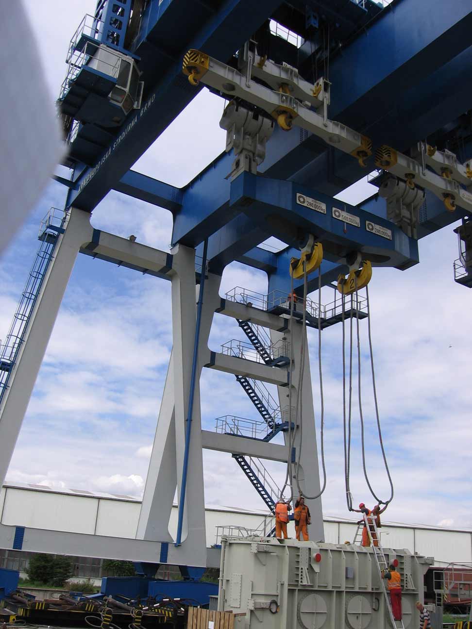
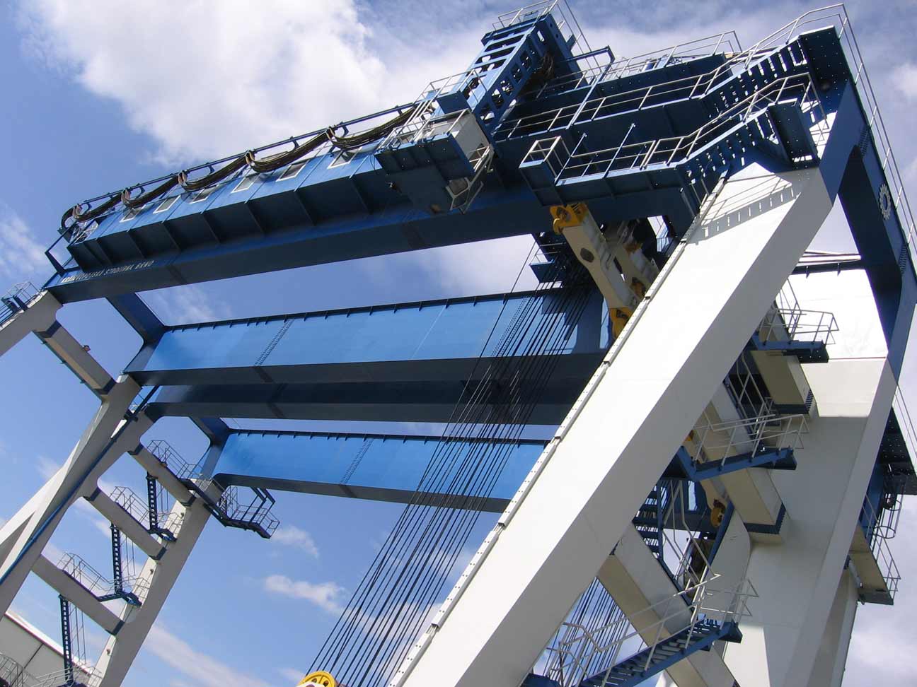
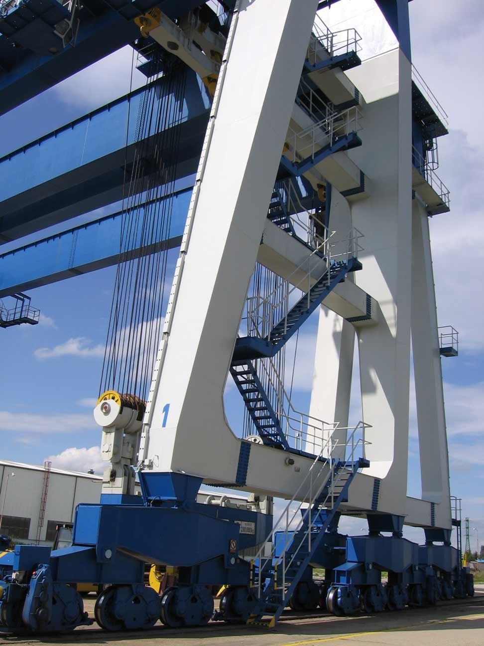
The crane is located in Bratislava, Slovakia, on the Danube River. It has a capacity of 560 tons.
This crane is actually two cranes, that can be joined together to lift a maximum of 560 tons.
The following photos were sent to me by Ivan Rojnica. They clearly show how the two cranes work in concert, with a single spreader bar.

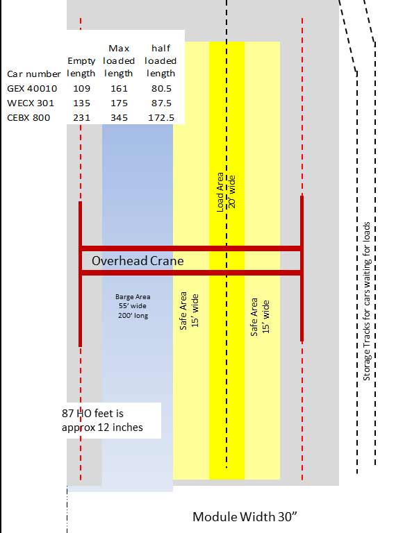
Port Area Drawing
Once I settled on modeling the crane at Bratislava, I needed a drawing to scale the crane, and the dock area. The water area had to be big enough to hold both the barge and tow boat made by Custom Model Railroads. The barge is 90 scale feet long and the tow boat is about 60 feet long. The largest schnabel car, CEBX 800, with load must fit under the crane.
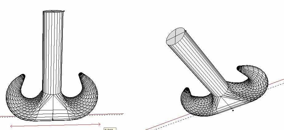
3D Printed Hooks
The gantry crane will need at least two hooks. I had been looking for some hooks for a while, when Patrick (another Southern Railway modeler from Beaufort, S.C.) pointed me to an O Scale hook on EBay. This hook was perfect for my HO Scale needs. But I will need more than one, and could not find any more.
I decided to try and make these with 3D printing. Opened SketchUp a free 3D CAD tool. I searched their library for a crane hook, and found one that looked like it would work, downloaded it, and then scaled it down to HO scale. The completed file was uploaded to Shapeways.
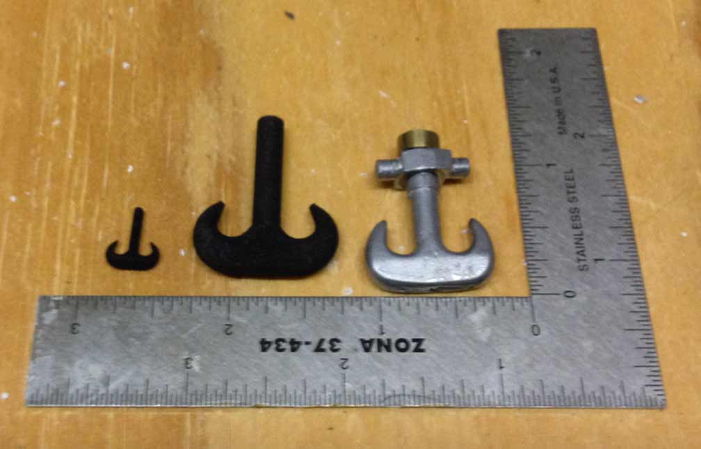
About three weeks later, the hooks show up. They were not the correct size. Opened up the SketchUp file, and I had scaled it in mm, when I was thinking/designing in inches. After fixed the sizing, the updated file was uploaded back to Shapeways. Another three week wait, and the new hooks arrive. Perfect, just over 1 inch wide!
The right most photo below shows the first try, which turns out to be too small. Next is the correctly sized one, followed by the one purchased from EBay.
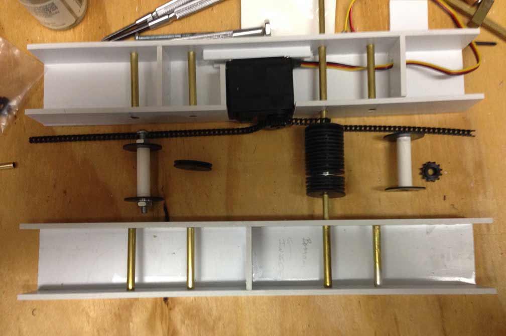
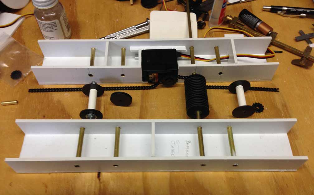
The crane trolley
I have started working on the trolley. The size of it is based on the servo that will be used to power the lift. This one servo will control two spools and two sets of pulleys. The servo will connect to the lift spools via a chain and sprocket. The servo has been modified to rotate continuously. Did not quite finish, I ran out of brass tubing. I will have to take more photos later, when the two sides are connected. I need to get a smaller gear that will control the side to side movement. This gear size will control the size of the structure that connects the two sides.
About 40 pulleys will be needed for the crane and the two sheaves. These are made from black sheet styrene from Evergreen Scale Models, and their construction is covered in the 2012 blog.
I am not happy with the width of the trolley's body. I am planning to go back and build the second version, where the servo is not in the body.
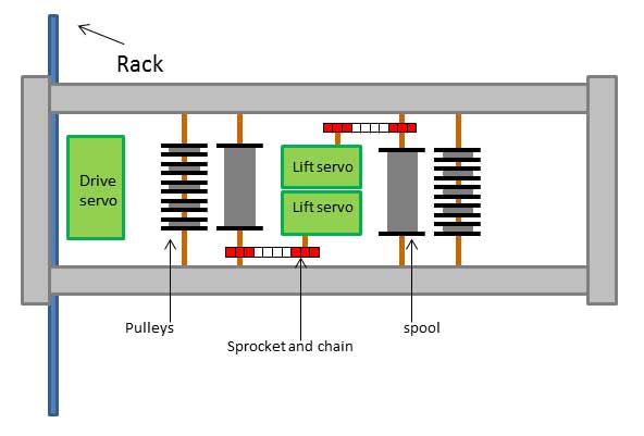
In planning for the crane's trolley, I have the following requirements. It needs to have two hooks that lift, and it needs to move side to side.
The first version has two servos motors for lifting the hooks. The spools are connected to the servos with sprocket and chain.
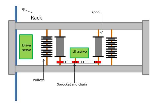
The second version has one servo motor that is connected to both spools with sprocket and chain.
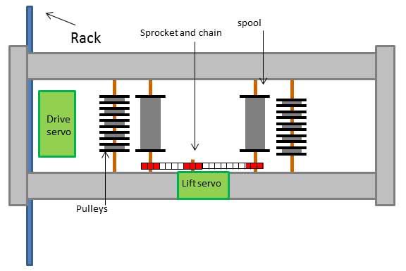
The third version moves the servo motor into the trolley body. This is the version that I am going to build.
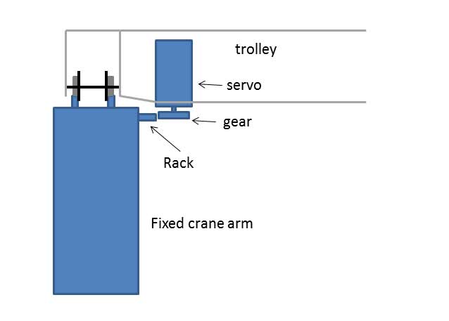
The last drawing shows how a second servo motor will be used to move the trolley back and forth.
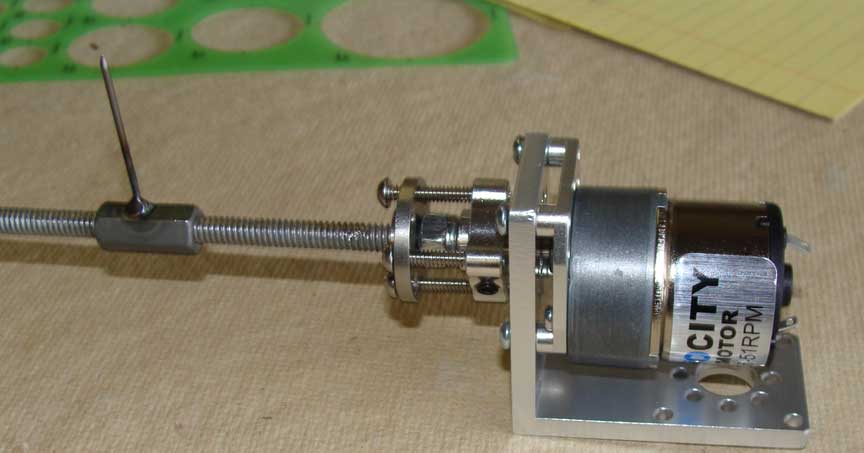
Motorizing the Gantry Crane
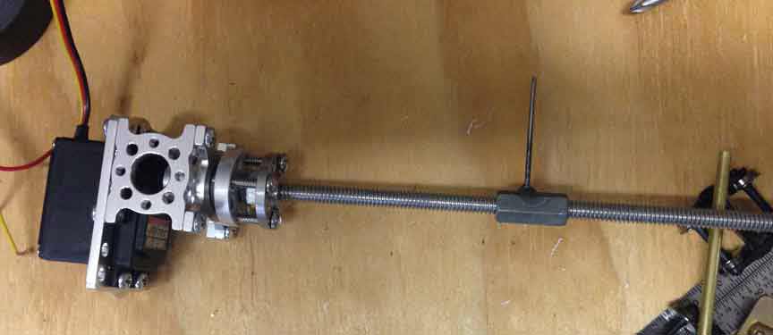
The gantry crane needs to move the length of the dock, but very slowly. I have thought of many ways to move the crane. I finally decided upon coupling nut running down a threaded rod. A friend connected me with Al (the welder from South San Francisco), who welded the nail onto the nut. I modified a RC Servo to rotate continuously. When mounted on some hardware from Servo City, it appears to be what I need. But when the servo is connected up to a battery, there is a fair amount of wobble. I will need to keep looking for a new slow speed motor.
Linear Drive - version 2
I have now resolved the wobble with a new motor from Servo City. The travel on this version is very smooth. I can control this one with a DCC controller.